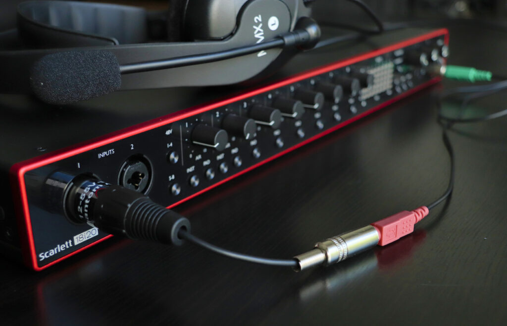
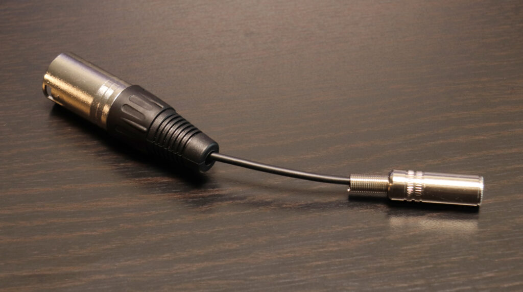
This adapter makes it possible to connect a standard PC headset or microphone to a professional audio interface with XLR connectors and 48V phantom power. In my case the noise floor of the microphone was improved by about 30dB over the standard microphone inputs of my laptop and PC.
Microphones intended for use in conjunction with a laptop or standard pc sound card usually come with a 3.5mm TRS style jack and take 2.5V – 5V of phantom voltage. To use them on the professional XLR style microphone connections not only the pulg type has to be adapted, but also the phantom voltage has to be reduced from the professional 48V level down to 3.3V. This circuit works well from 12V to 65V phantom power.
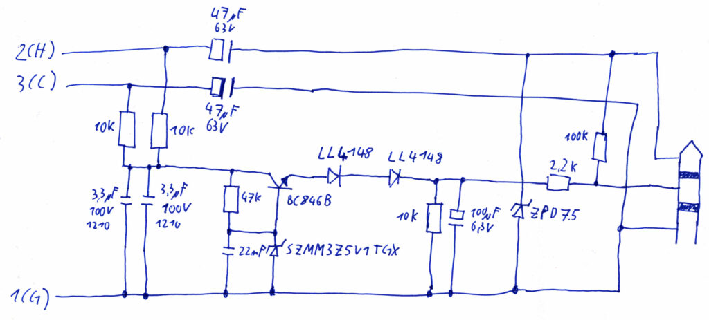
Here is the schematic:
A few notes:
- The Frequency response starts at 2.5Hz. (-3dB point if the interface provides only a 2kOhm input impedance. Even lower for higher input impedances.)
- On my headset the noise floor is about 45dB below the normal speech level.
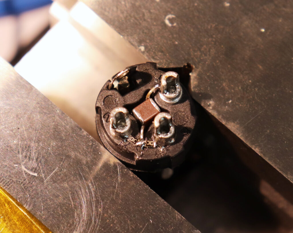
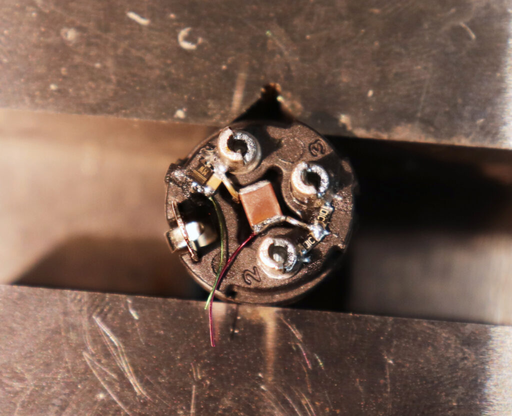
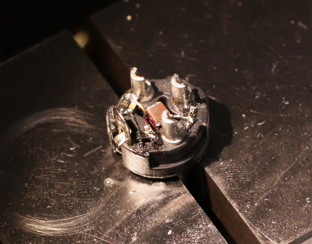
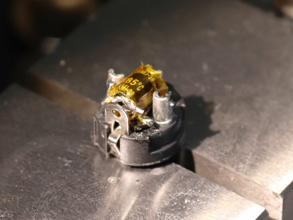
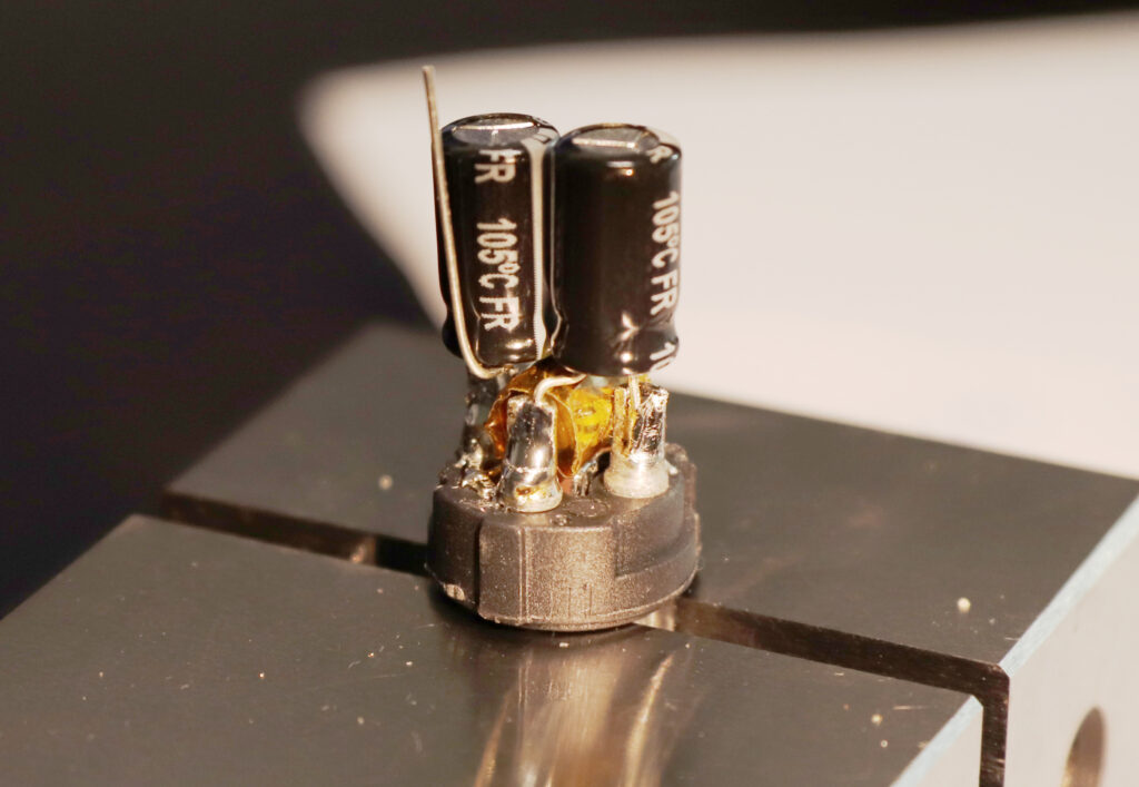
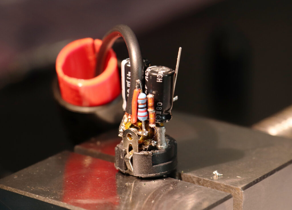
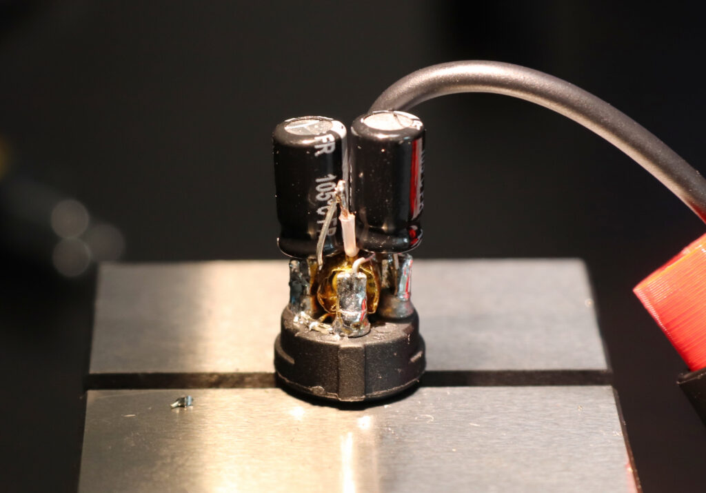
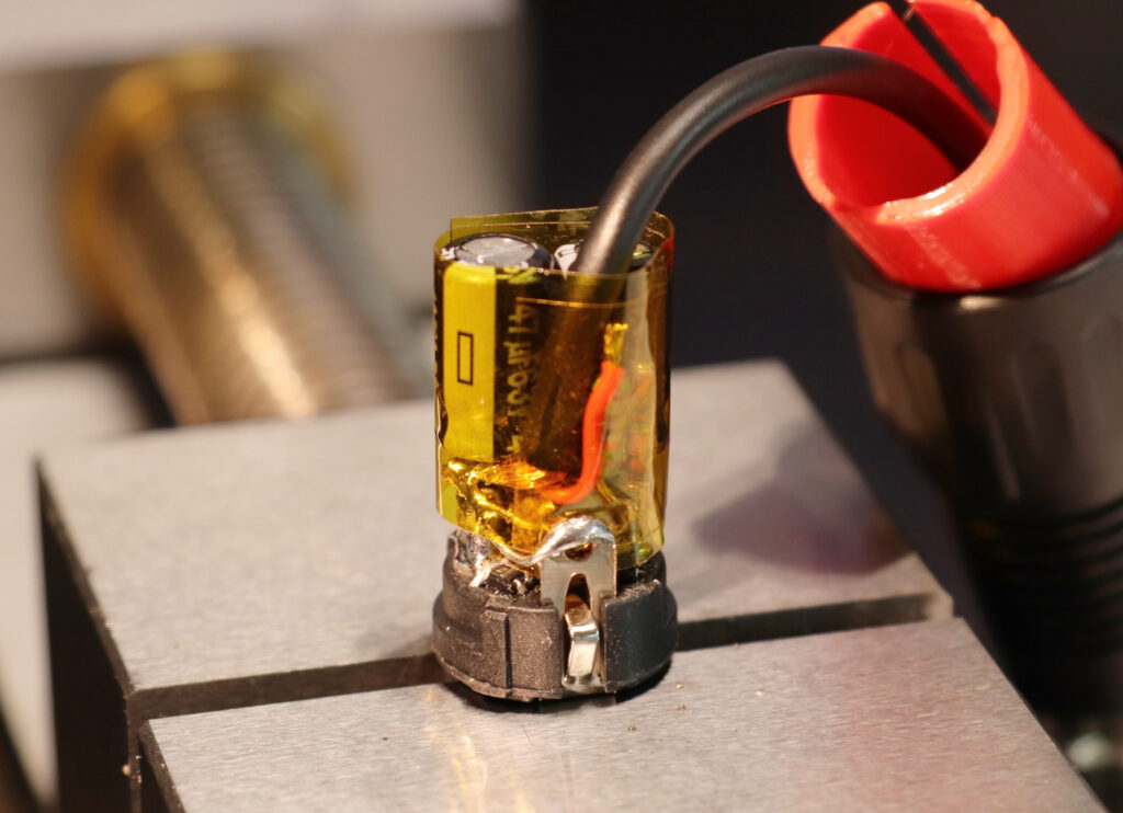
- Everything fits into a standard XLR connector.
- I first tried an LDO regulator but they are way too noisy without extensive filtering. Extensive filtering is too big to neatly fit inside an XLR connector. An emitter follower with a Z-Diode for reference is better by several orders of magnitude.
- I went with a 5.1V Zener diode because this is the first diode in the series which voltage is very constant over a large range of currents. The large range is needed in order to provide a good stability over a large range of input voltages. If possible use this specific type.
- The two LL4148 together witht he base-emitter voltage reduce the output voltage to about 3.3V.
- The 10kOhm resistor in parallel to the 100µF output capacitor provides a base load, so that the LL4148s and the BE-juntion are biased into their steep region, i.e. the voltage drop over them is stable for any output load.
- The ZPD75 between the signal coming from the mic and GND is for protecting the microphone when the 48V phantom voltage changes very abruptly. You might want to use lower values (e.g. 5.1V). The 100kOhm is for DC level biasing of the Zener in case the mic has a decoupling cap in the signal line.